Module - 1: Number Systems & Boolean Algebra
On completion of this module, you will be able to:
- Understand what is Number Systems ?
- Understand different number systems like Binary, Octal, Decimal, Hexadecimal
- Understand Karnaugh Maps and their use for simplification of Boolean expressions
- De-Morgan’s Theorem
Number System
- In digital electronics, the number system is used for representing the information.
- The number system has different bases and the most common of them are the decimal, binary, octal, and hexadecimal.
- The base or radix of the number system is the total number of the digit used in the number system.
- Suppose if the number system representing the digit from 0 – 9 then the base of the system is the 10.
Types of Number Systems
- Some of the important types of number system are
1. Decimal Number System
2. Binary Number System
3. Octal Number System
4. Hexadecimal Number System

Decimal Number System
- The decimal numbers are used in our day-to-day life. The decimal number system contains ten digits from 0 to 9(base 10).
- Here, the successive place value or position, left to the decimal point holds units, tens, hundreds, thousands, and so on.
- The position in the decimal number system specifies the power of the base (10). The 0 is the minimum value of the digit, and 9 is the maximum value of the digit.
- For example: - the decimal number 2541 consist of the digit 1 in the unit position, 4 in the tens position, 5 in the hundreds position, and 2 in the thousand positions and the value will be written as:

Binary Number Systems
- The modern computers do not process decimal number, they work with another number system known as a binary number system which uses only two digits 0 and 1.
- The base of binary number system is 2 because it has only two digit 0 and 1. The digital electronic equipment’s are works on the binary number system and hence the decimal number system is converted into binary system.
- Characteristics:
- It holds only two values, i.e., either 0 or 1.
- It is also known as the base 2 number system.
- The position of a digit represents the 0 power of the base(2). Example: 20
- The position of the last digit represents the x power of the base(2). Example: 2x, where x represents the last position, i.e., 1
Examples are:
- 10101 - is a five-bit binary number
- 101 - is a three-bit binary number
- 100001 - is a six-bit binary number
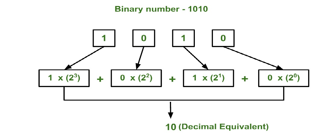
Example 1: Convert binary number (1010) to an equivalent decimal value.
Solution:
Octal Number System
- The decimal numberslife. The decimal number system contains ten digits from 0 to 9(base 10).
- The octal number system has base 8(means it has only eight digits from 0 to 7). There are only eight possible digit values to represent a number.
- With the help of only three bits, an octal number is represented. Each set of bits has a distinct value between 0 and 7.
- There are the following characteristics of the octal number system:
- An octal number system carries eight digits starting from 0, 1, 2, 3, 4, 5, 6, and 7.
- It is also known as the base 8 number system.
- The position of a digit represents the 0 power of the base(8). Example: 80
- The position of the last digit represents the x power of the base(8). Example: 8x, where x represents the last position, i.e., 1
 Example: Convert an decimal number (33) to an equivalent octal number.
Solution:
Example: Convert an decimal number (33) to an equivalent octal number.
Solution:
 Example: Convert an octal number (123) to an equivalent decimal value.
Solution:
Example: Convert an octal number (123) to an equivalent decimal value.
Solution:

Hexadecimal Number System
- It is another technique to represent the number in the digital system called the hexadecimal number system.
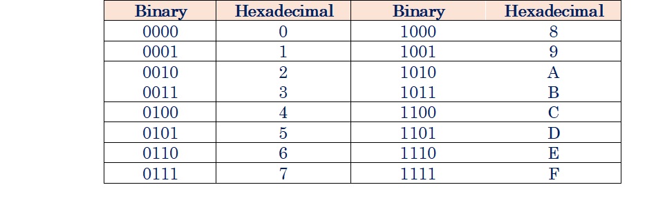
- The number system has a base of 16 means there are total 16 symbols(0, 1, 2, 3, 4, 5, 6, 7, 8, 9, A, B, C, D, E, F) used for representing a number.
- The single-bit representation of decimal values 10, 11, 12, 13, 14, and 15 are represented by A, B, C, D, E, and F.
- Only 4 bits are required for representing a number in a hexadecimal number. Each set of bits has a distinct value between 0 and 15.
- There are the following characteristics of the hexadecimal number system:
- It has ten digits from 0 to 9 and 6 letters from A to F.
- The letters from A to F defines numbers from 10 to 15.
- It is also known as the base 16 number system.
- In hexadecimal number, the position of a digit represents the 0 power of the base(16). Example: 160
- In hexadecimal number, the position of the last digit represents the x power of the base(16). Example: 16x, where x represents the last position.
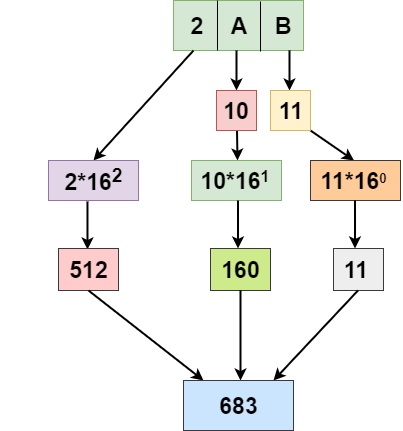
Example 1: Convert an hexadecimal number (2AB) to an equivalent decimal value.
Solution:
Example 2: Convert an hexadecimal number (A12C) to an equivalent binary number.
Solution: The process to convert the hexadecimal number to binary number is given below
- Hexadecimal number = A12C
- Binary value equivalent to A is 1010
- Binary value equivalent to 1 is 0001
- Binary value equivalent to 2 is 0010
- Binary value equivalent to C is 1100

Example 1: Decimal to binary conversion
Example 2: Decimal to binary conversion
Example 3: Binary to decimal conversion
Boolean Algebra
- Boolean Algebra is a set of rules which are used to simplify the given logic expression without changing its original functionality.
- The Boolean algebra was invented by mathematician George Boole in 1854, who is considered the “Father of symbolic logic”.
- It is used to analyze and simplify the digital(logic) circuits. It uses only the binary numbers i.e. 0 and 1. So, the variables used in Boolean Algebra can have only two possible values, 0 or 1.
- The Boolean algebra is mainly used for simplifying and analyzing the complex Boolean expression. It is also known as Binary algebra because we only use binary numbers in this.
Rules in Boolean Algebra
- In Boolean Algebra the uppercase letters are usually used to represent variables and functions of variables
- Any single variable or a function of several variables can have value of either 1 or 0 only. The binary digits are used to represent the two levels in the digital logic circuits. A binary ‘1’ represents a High level and a binary ‘0’ represents a Low level in Boolean equations(positive logic)
- Complement of a variable is represented by Bar. Logical AND function is represented by ‘ . ’ Symbol. and Lgical OR function is represented by ‘ + ’ symbol
Boolean Law : There are six types of Boolean Laws
- Commutative Law
- A+B = B+A --------> Law of Addition
- A.B = B.A --------> Law of Multiplication
- Associative Law -
- (A.B).C = A.(B.C)
- ( A+B )+C = A + (B + C)
- Distributive Law –
- AND law – These laws use the AND operation therefore they are called AND Laws
- A.0 = 0 (ii) A.1 = A (iii) A.A = A (iv) A. A’ = 0
- OR Law - These laws use the AND operation therefore they are called AND Laws
- A + 0 = A (ii) A +1 = 1 (iii) A+A = A (iv) A + A’ = 1
- INVERSION Law – this law uses the NOT operation. The inversion law states that double inversion of a variable results in the original variable itself
Logical Operators:
- There are three logical operator, NOT, OR and AND. These operators are now used in computer construction known as switching circuits.
- NOT Operator:
- The Not operator is a unary operator. This operator operates on single variable and it is called complementation.
- The symbol we use for it is bar. X means complementation of X .
- If X=1, X=0 and If X=0, X=1
- The Truth table and the Venn diagram for the NOT operator is shown below:

- OR Operator:
- The AND operator is a binary operator. This operator operates on two variables.
- The operation performed by OR operator is called logical addition.
- The symbol we use for it is ‘+’. for example: X + Y can be read as X OR Y
- The Truth table and the Venn diagram for the OR operator is shown below:

- AND Operator:
- The AND operator is a binary operator. This operator operates on two variables.
- The operation performed by AND operator is called logical multiplication.
- The symbol we use for it is ‘.’. for example: X . Y can be read as X AND Y
- The Truth table and the Venn diagram for the AND operator is shown below:

Boolean Theorems:
- Boolean Theorem can be proved by substituting all possible values of the variable that are 0 and 1. This technique of proving theorem is called Proof by perfect induction.
| S.N. |
Theorem |
Boolean Law |
S.N. |
Theorem |
Boolean Law |
| 1. |
0 + X = X |
Properties of 0 and 1 |
12. |
X .(Y.Z) = (X.Y).Z |
Associative Law |
| 2. |
1 + X = 1 |
Properties of 0 and 1 |
13. |
(X+Y).Z = X+(Y.Z) |
Associative Law |
| 3. |
0 . X = 0 |
Properties of 0 and 1 |
14. |
X.(Y+Z) = X.Y + X.Z |
Distributive Law |
| 4. |
1 . X = X |
Properties of 0 and 1 |
15. |
X+Y.Z = (X+Y).(X+Z) |
Distributive Law |
| 5. |
X + X = X |
Indempotence Law |
16. |
X + XY = X |
Absorption Law |
| 6. |
X . X = X |
Indempotence Law |
17. |
X(X+Y) = X |
Absorption Law |
| 7. |
X + X = 1 | Complementary Law |
18. |
XY + X = X | Absorption Law |
| 8. |
X . X = 0 | Complementary Law |
19. |
(X+Y)(X+ = X | Absorption Law |
| 9. |
X =X | Involution Law |
20. |
X+ Y = X+Y | Absorption Law |
| 10. |
X . Y = Y . X | Commutative Law |
21 |
X( +Y) = XY | Absorption Law |
De Morgan’s Theorem
- De Morgan´s Theorem and Laws can be used to find the equivalency of the NAND and NOR gates. There are two theorems.
De Morgan’s First Theorem
- The complement of the sum of two or more variables is equal to the product of the complement of the variables.

Proof:
- The Boolean equation for NOR gate is

- The Boolean equation for a bubbled AND gate is

- Both cases generate same outputs for same inputs. It can be verified using the following truth table.
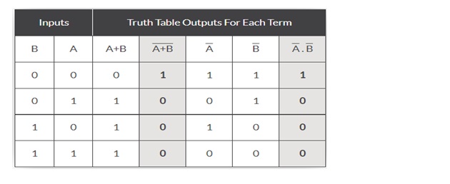
- From the above truth table, we can conclude
- Thus, De Morgan’s First Theorem is proved.
- It also says that a NOR gate is equal to a bubbled AND gate. The corresponding logic circuit diagram is shown in figure.

De Morgan’s Second Theorem
- The complement of the product of two or more variables is equal to the sum of the complements of the variables

Proof:
- The Boolean equation for NAND gate is

- The Boolean equation for bubbled OR gate is

- Where A and B are the inputs and Y is the output.
- The above two equations produce the same output for the same inputs. It can be verified by using the truth table.

- From the above truth table, we can conclude
- Thus, De Morgan’s Second Theorem is proved.
- It also says, a NAND gate is equal to a bubbled OR gate. The corresponding logic circuit diagram is shown in figure.

Karnaugh Maps
- Karnaugh map or K-Map is a pictorial method to simplify Boolean functions or expressions in digital electronics without using the Boolean algebra.
- In 1953, American physicist Maurice Karnaugh introduced this method. This is the easiest way to reduce any logic function to a simple form.
- It results in less number of logic gates and inputs to be used during the fabrication.
Rules for K-Map
- First draw the truth table cells corresponding to the given Boolean expression. You have to notice the number of variables. The number of cells in the truth table depends on the number of variables.
- If n be the number of variables, then the number of cells will be 2n. But remember, the number of rows must be less than or equal to the number of columns.
- For example:
- In 2 variables K-map, the number of cells will be 4. There will be 2 rows and 2 columns.
- In a K-map with 3 variables, the number of cells will be 8. There will be 2 rows and 3 columns. This is easy to understand in some examples given below.
- After drawing the cells, you need to develop the truth table by putting 1‘s in all possible cells according to given Boolean equation. Check the K-Maps with 2 variables, 3 variables and 4 variables at below for the better understanding.
- We can either group 0’s with 0’s or 1’s with 1’s but we cannot group 0’s and 1’s together. X representing don’t care can be grouped with 0’s as well as 1’s.
- There is no need of separately grouping X’s i.e. they can be ignored if all 0’s and 1’s are already grouped. Groups may overlap each other.
- Grouping must be done with 8, 4 or 2 neighbour 1‘s (whichever is greater). In other words, a group can only contain 2n i.e. 1, 2, 4, 8, 16 and so on number of cells.
- Take the common variables in row and column of each group of 1’s and write those variables in multiplication form. Now, take the sum of each product of variables from the groups.
- This will be the final simplified form of that Boolean expression.
Two Variable K-Map
- Two variable K-Map is drawn for a Boolean expression consisting of two variables. The number of cells present in two variable K-Map is 22 = 4 cells.
- So, for a Boolean function consisting of two variables, we draw a 2 x 2 K-Map.
- Two variable K-Map may be represented as

- Here, A and B are the two variables of the given Boolean function.
Three Variable K-Map
- Three variable K-Map is drawn for a Boolean expression consisting of three variables. The number of cells present in three variable K-Map is 23 = 8 cells.
- So, for a Boolean function consisting of three variables, we draw a 2 x 4 K-Map.
- Three variable K-Map may be represented as

- Here, A, B and C are the three variables of the given Boolean function.
Four Variable K-Map
- Four variable K-Map is drawn for a Boolean expression consisting of four variables.
- The number of cells present in four variable K-Map is 24 = 16 cells.
- So, for a Boolean function consisting of four variables, we draw a 4 x 4 K-Map.
- Four variable K-Map may be represented as

- Here, A, B, C and D are the four variables of the given Boolean function.
- Example 1: Reduce the function given below using K-map.
F(A, B, C) = ∑ m (1, 3, 6, 7)
- Solution:
- We know that the number of cells of the K-map is dependent on the number of variables. So, for 3 variable K map, the number of cells will be 23 i.e., 8 .
- The figure below represents the K-map for 3 variables having 8 cells.

- The figure below shows the assigning of bits to the K-map.

- Here, we can clearly see that for minterm K-map, 1 is assigned at m0, m1, m2, m4, m7, as given in the function.
- The figure below represents the grouping of bits for the above function:

- Here, we can see that two 1, present at the 1st row of column 00 and 01 are forming pair.
- Similarly, two 1’s of the first column and rows 0, 1 are forming a pair.
- Also, the two corners, 1 at the first row is forming a group of 1.
- However, still, a single 1 is left that is unable to participate in a grouping as no other 1 is present at its adjacent position. So, this 1 is considered to be as a group of single 1. As represented in the figure given above.
- Let us now see how the above function is realized using K-map.So, the function for all 4 groups will be:
I Group = A . B
II Group = B . C
III Group = A . C
IV Group = ABC
- So, combinely the realized Boolean expression will be given as:
F = A . B + B . C + A . C + ABC
- Example 2: Reduce the function given below using K-map.
F(A, B, C) = ∑ m (0, 1, 2, 4, 7)
- Solution:
- The figure below shows the assigning of bits inside the K-map.

- The figure below represents the grouping of bits for the above function:

- So, combinely the realized Boolean expression will be given as:
F = AB + BC + A . C
- Here redundancy of bit is generating. This is so because the two 1’s present at BC position is already grouped individually with their adjacent bit.
- So, in this case, the group BC will be ignored and the realized Boolean expression will be:
F = AB + A . C


